
Accede a información sobre la estructura de la actividad investigadora de Geintra.
Trabaja con nosotros
Accede a nuestra oferta actual de becas, tesis doctorales, contratos y trabajos fin de carrera.
Demos
In this page you'll find several demonstrations of the GEINTRA available technology.
- Self-triggered Formation Control of Nonholonomic Robots
- Event-based sensing and control for remote robot guidance: experimental case
- Indoor mobile robot localization using PSD sensor
- Mobile robot localization with Multiple Ultrasonic LPSs and odometry
- Ultrasonic LPS using Generalized Cross-Correlation
- Intelligent Guiding of Wheel Chairs
- Ultrasound Indoor Location System
- Intelligent Transport Systems for Cooperative Guidance of Electrical Vehicles
- Robot Routing Considering Uncertainties in Travelling Times
- Self-triggered control of a remotely operated P3-DX robot
- Remote adaptive self-triggered control for trajectory tracking of two P3-DX robots
- Human-machine interfaces based on Active Appearance Models (AAMs)
- Acoustic based speaker localization systems
- Video based localization and tracking systems
- Video based full body tracking systems
Media coverage:
Self-triggered Formation Control of Nonholonomic Robots
The video describes the implementation of a self-triggered remote road-following formation controller applied to nonholonomic robots tracking nonlinear trajectories using an external positioning sensor network.
The starting point is the design of a novel self-triggered Lyapunov-based controller, using a dual stability approach in order to guarantee practical stability.
The test is carry out with three Pioneer P3DX robots. The remote centre control is implemented in a NUC5i3RYH mini PC linked to the robot through an IEEE 802.11g wireless channel. The test area is sensed by four Kinect 2 cameras connected to an identical mini PC. All mini PCs run Ubuntu 12.04, as operating system. An AprilTag marker is situated on the top of each P3DX robot to obtain its pose using the AprilTags fiducial system. (you can also get the full quality avi file 148Mb).
Event-based sensing and control for remote robot guidance: experimental case
This video demonstrates an experimental case of event-based sensing and control combination. A robot tracks a non-linear trajectory using the commands remotely sent by a remote center and the pose captured by a camera. The aperiodic global solution allows an efficient use of the communication channel and a significant reduction of the sensor activity (you can also get the full quality avi file
18Mb).
Indoor mobile robot localization using PSD sensor
This video shows the operation of an indoor positioning system based on a
single sensor PSD. This system is able to determine multiple agents
simultaneously; it has a fast update-rate until 500 times per second with
a low SNR. Computational process is based solely on the calculation of the
RMS value of 4 signals (you can also get the full quality wmv file (77Mb).
In the video:
- Blue: Position obtained by the a Kinect camera.
- Green and red: Position obtained by the sensor PSD
Mobile robot localization with Multiple Ultrasonic LPSs and odometry
This video shows the operation of a Local Positioning System for Wide areas using Ultrasounds (U-WLPS). For the localization of a mobile robot both its onboard ondometry system and six single ultrasonic localization subsystems U-LPS are used. The positions obtained using the U-LPS (when available) are used to correct the odometry. The positions obtained by both positioning systems are merged using a H-infinite filter.
In the video:
- Top left is the actual movement of the mobile robot. It is speeded up by a factor x2 in the video to the left, and at normal speed in the video to the right.
- The rest of the image is the plan of the floor and the trajectory followed by the robot (with a zoom in the top right side). With:
- the blue dots are the beacons' projections of the US-LPSs (five beacons each).
- the green dots are the positions obtained with the LPS (when available).
- the red trajectory is the one obtained using only the odometry system.
- the black trajectory is the one obtained after combining positions from the LPS and odometry systems using the H-inf filter. It can be seen that through the filter H-infinity the robot is able to recover from cumulative errors caused by odometry outside the coverage areas of each single LPS. Furthermore, this filter smoothes erroneous measurements from ultrasound systems.
Ultrasonic LPS using Generalized Cross-Correlation
This video shows the performance of an ultrasonic LPS system composed of five beacons on the ceiling that emit synchronoulsy. Each one of the beacons has assigned a 1023-Kasami code that modulates a carrier signal of about 40kHz. The receiver, on the mobile, performs a discriminatation of the signals coming from the different beacons by correlation, calculates the Time Difference of Arrivals and performs the positioning using trilateration. In the video:
- The mobile follows a constrained circular trajectory, as ground truth.
- Different reflectors provoke multipaht (the worst situation for a US-LPS system).
- In the last part of the video a drill machine is turned on introducing a big amount of acoustic noise.
- To see:
- Top left: real movement, on the screen of the computer the actual signal captured by the receiver.
- Top center: calculated positions, in black using standard cross-correlation (CC) and in red using GCC.
- Top right: A zoom of the top-center image.
- The bottom part of the video is composed of ten figures: the upper part of them correspond to the CC for each one of the beacons and the lower part correspond to the GCC.
Intelligent guiding of wheel chairs
- Advanced Guiding of Wheel Chair (2005): This sequence
shows the behaviour of a non-contact Head Controller over an
advanced wheelchair (SIAMO prototype). Using only head movements
this user is able to go into a standard elevator; this is done
without pressing or moving any kind of physical device. The key of
the system is a patented IR detector that locates user's head an
evaluates its movements according to a predefined set of
commands. This work was made in 2005, in the Electronics Department
of the University of Alcala (Spain, www.geintra-uah.org); the IR
detection algorithm was designed by Mr. Henrik Vie Christensen (who
drives the chair) from the Dept. of Control Engineering, of the
Aalborg University (Denmark). - SIAMO Intelligent Wheelchair (1996-1999): This video shows a short resume of SIAMO project (SIAMO = Integral System for Assisted Mobility). Audio track is in Spanish. This project was under development between 1996 and 1999 in the Electronics Dpt. of the University of Alcala (Spain, www.depeca.uah.es). Main focus was to study, design and test several Human Machine Interfaces over an advanced wheelchair platform, also designed by the same research group. More information in: www.geintra-uah.org/en
- UMIDAM Intelligent Wheelchair (1991-1994): This video shows a short resume of an Intelligent Wheelchair called UMIDAM (UMIDAM = Intelligent Mobile Unit of Assisted Mobility). Audio track is in Spanish. This project was under development between 1991 and 1994 in the Electronics Dpt. of the University of Alcala (Spain, www.depeca.uah.es). A first prototype, controled by vocal commands, was shown inside the ONCE stand in the EXPO'92 of Sevilla (Spain). More information in: www.geintra-uah.org/en
Ultrasound Indoor Location System
- Ultrasound Indoor Location System (2009): This sequence shows the behaviour of an experimental ILS (Indoor Location System) based on codified Ultra Sound beacons. This research have been made in the GEINTRA labs of the University of Alcala (Spain) in 2009; web-page: http://www.geintra-uah.org/en. In this video, ILS uses LS (Loosely Synchronized) codes to measure accurately the TOF (Time Of Flight) between the target and a set of reference beacons. To demonstrate system behaviour a mobile robot moves inside the ILS coverage area; while moving, two different set of data can be seen on screen: conventional odometry is shown with a green line; ILS positioning is shown unfiltered (red line) and filtered (black line). Around second six, the robot is taken up while running: odometry estimation show a growing error as expected, while ILS estimation remains low and keep track of moving object in any time.
Intelligent Transportation System for Cooperative Guidance of Electrical Vehicles in Special Scenarios (COVE project 2010)
This research project deals with the design and implementation of an electronic architecture (sensorial, control and communication) that contributes to the cooperative guidance of transport units: platoon formed by electrical vehicle prototypes.
The following results have been achieved: Development and implementation of control solutions so that the followers units can automatically perform a stable leader-following process in non-linear trajectories. Design and implementation of algorithms which deal with merge and split manoeuvres of units related to a convoy. Design of an intelligent system for attendance to the leader in the decision making process on the optimal and efficient route, according to previous experiences.
The following videos show several experimental tests carried out in the laboratories of the Polytechnic School at the University of Alcala, using P3-DX robotic units as electrical vehicle prototypes. The convoy departs from one laboratory, moves along a corridor and arrives to the adjoining laboratory (video sequence 1) or to the original one (video sequence 2).
- Video sequence 1 (direct link to wmv video, in case you have problems with flash)
- Video sequence 2 (direct link to wmv video, in case you have problems with flash)
Robot Routing Considering Uncertainties in Travelling Times (2011)
This section shows two demonstrations of robot routing in a real simplified transport scenario, showed in the following figure.
There are two Pioneer P3-DX units, one of them working as a convoy leader continuously moving around the periphery, and another identical robot working as a pursuer which challenge is to merge the convoy in the optimal meeting point (minimum merging time).
The scenario includes different areas with different statistical values (mean and variance) of velocities (see figure), this way a random velocity is dynamically assigned to each robot once a new node is reached. In order to delimit the randomness inherent to the problem, the parameter “risk factor” is considered, limiting the probability of the convoy reaching the merging node before the pursuer (failed merging maneuver).
- The first video was taken in the most conservative condition (0% risk factor). The meeting point is decided in order to reduce the probability of failure, but the waiting time is notably large (direct link to mpg video (61MB), in case you have problems with flash)
- The second video was taken in the less conservative condition (100% risk factor). In this case, the required time for the meeting maneuver has been considerably reduced. However the number of re-planning for the pursuer unit has increased as well as the number of the percentage of failed tests (direct link to mpg video (92MB), in case you have problems with flash)
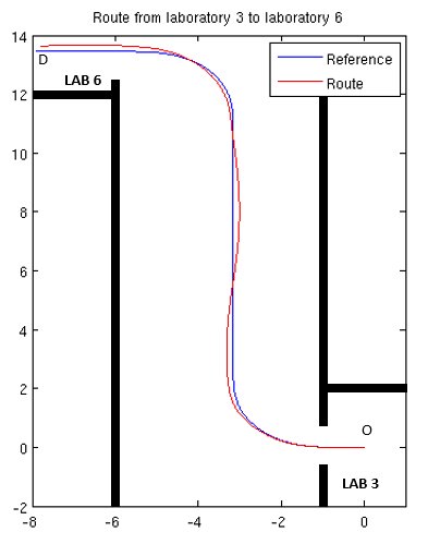
Self-triggered control of a remotely operated P3-DX robot (2013)
This video shows an example of self-triggered application to the remote control of a robotic unit. Figure 1 displays the trajectory followed by the robot which is controlled by a PC through a wifi link. The classical sampled digital control is replaced by a self-triggered solution according to scheme control of Figure 2. (you can also get the full quality wmv file (66Mb))
| Figure 1 | Video |
|
|
Figure 2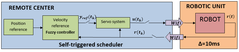 |
|
Remote adaptive self-triggered control for trajectory tracking of two P3-DX robots (2013)
The video shows the trajectory tracking of two robotic units simultaneously controlled by a remote centre through wireless link (WLAN IEEE 802.11g). An adaptive self-triggered control solution has been implemented considering the effect of time-varying network delays, only the information provided by the odometric system is feedbacked for trajectory tracking. On the left-hand side the trajectory followed by the robots at the laboratory area is included. On the right-hand side the tracking error and the inter-sampling time is dynamically plotted. This research work has been made in the GEINTRA labs of the University of
Alcala (Spain) in 2013 (you can also get the full quality mp4 file (63Mb)).
Human-machine interfaces based on video processing
- Virtual mouse based on face tracking techniques (2010): The video shows a very simple HMI (Human-Machine Interface) based in AAMs (Active Appearance Models). The user is able both to move a cursor around the screen only with head movements, and simulate a mouse left click opening the mouth (you can also get the full quality avi file).
Acoustic based audio localization systems
- SRP-PHAT based acoustic localization system: The green sphere represents ground truth
speaker position, and the red one is the system location
estimation. No tracking is attempted, just plain memoryless
localization. The SRP-PHAT power grid is partially shown, with the
cube intensity being related to the the received signal power in the
corresponding grid location (you can also get the full quality video file). - Microphone arrays modeled as perspective cameras (3D map, short footage): Acoustic 3D map estimated from a single microphone array modelled as a
perspective camera. x and y axes represent angle variations in azimuth
and elevation, respectively, with the array center being the local
coordinate center. The z axe represents acoustic power coming from the
corresponding direction in 3D space (azimuth, elevation). The
microphone array is composed by 4 elements, three of them linearly
aligned and the third one orthogonal to the others (inverted
T-shape). The speaker is slightly moving during the sequence (you can also get the full quality video file). - Microphone arrays modeled as perspective cameras (2D map, long footage): Acoustic 2D map generated from the 3D surface estimation described
above. In this case, ground truth is also shown as a red circle (the
ground truth being the circle center). x and y axes represent angle
variations in azimuth and elevation, respectively, with the array
center being the local coordinate center. The speaker is slightly
moving during the sequence (you can also get the full quality video file). - Microphone arrays modeled as perspective cameras (2D map): Acoustic 2D map generated by a linear microphone array composed of four equispaced microphones
(so that only azimuth can be identified. x and y axes represent angle
variations in azimuth and elevation, respectively, with the array
center being the local coordinate center. The speaker was static
during all the sequence (you can also get the full quality video file). - Sector based acoustic localization using multiple arrays: Demonstration of sector based localization, using two circular
arrays. The system identifies the active sectors for each array and
run a SRP-PHAT algorithm in the intersection to determine the speaker
position. The black circle is the ground truth position, and the red
one is the estimated location. The active intersections are highligted
also in red (you can also get the full quality video file).
Video based localization and tracking systems
- Real time client server system for target tracking applications: Real-time client-server system running the video based tracking
task. Each server operates on the frames captured by a single
camera. The client connects with the server and integrates the
information coming from multiple views (you can also get the full quality video file). - XPFCP based tracker (using a 2D grid): XPFCP based tracker, using a 2D grid estimation and target projections
on the floor. Each target is given a certain target ID
(color). Sequence obtained in the former GEINTRA lab (you can also get the full quality video file). - XPFCP based tracker (using a 3D grid): XPFCP based tracker, using a 3D grid estimation and target projections
on the floor. Each target is given a certain target ID (color) and a
clustering procedure tries to identify different targets in the 3D
space. Sequence obtained in the new GEINTRA Intelligent Space Lab (you can also get the full quality video file).
Video based full body tracking systems
- Skeleton tracker running on a single person: (you can also get the full quality video file).
- Skeleton tracker running on two persons: Skeleton tracker running on two persons (only one actually exists and
the other is artificially generated copying observation data from a
different video sequence) (the full quality video file).